Published Book on Amazon
| All of IOT Starting with the Latest Raspberry Pi from Beginner to Advanced – Volume 1 | |
| All of IOT Starting with the Latest Raspberry Pi from Beginner to Advanced – Volume 2 |
출판된 한글판 도서
| 최신 라즈베리파이(Raspberry Pi)로 시작하는 사물인터넷(IOT)의 모든 것 – 초보에서 고급까지 (상) | |
| 최신 라즈베리파이(Raspberry Pi)로 시작하는 사물인터넷(IOT)의 모든 것 – 초보에서 고급까지 (하) |
Original Book Contents
25.8.3 Utilizing Digital DHT11 Humidity/Temperature Sensor
25.8.3.1 Feature of the Sensor
Here, we will use a module that integrates DHT11 sensor and other necessary components on a small PCB as shown below. The DHT11 sensor is equipped with resistive humidity measurement components, NTC temperature measurement components, and a high-performance 8-bit microcontroller and provides precise digital signal output. The DHT11 sensor originally has four wires, but this module has three wires.
| No | Pin | function |
| 1 | - | ground |
| 2 | + | power |
| 3 | S | Digital data line |
|
|

Figure 25‑21 Digital Humidity/Temperature Sensor Module DHT11
It has the following characteristics.
| Item | Description |
| Voltage range | 3.0V to 5.5V |
| Measurement range | Humidity 20-90%RH, Temperature 0~50℃ |
| Output | 4 pin single row |
| Accuracy | Humidity +-5%RH, Temperature +-2℃ |
| Resolution | Humidity 1%RH, Temperature 1℃ |
| Interchangeability | Fully Interchangeable |
| Long-Term Stability | <±1%RH/year |
● 자료 전송 방식
This sensor uses single bus data format for communication and synchronization between MCU (Micro-controller-Unit) and DHT11. Each communication processor is maintained for 4 ms, and the transmission data is transmitted in a total of 50 bits as follows.
■ Humidity data -- 8 bit integral RH data + 8 bit decimal RH data +
■ Temperature data -- 8 bit integral T data + 8 bit decimal T data +
■ Checksum -- 8 bit check sum.
If the data transmission is correct, the check sum should be equal to the lower 8 bits of the result of "8 bit integral RH data + 8 bit decimal RH data + 8 bit integral T data + 8 bit decimal T data".
The following figure is a general conceptual diagram for data transmission between MCU and DHT11.
|
|

The figure below shows the status of DATA pin in the phase of starting and synchronizing the communication between MCU and DHT11. The default state of DATA pin is "HIGH" state. When communication between MCU and DHT11 starts, the MCU pulls the DATA pin down to "LOW" state for at least 18ms. This is called "Start Signal" and is used to let the DHT11 start the transmission procedure. The MCU then puts the DATA pin in "HIGH" state for 20-40us and waits for the response of DHT11.
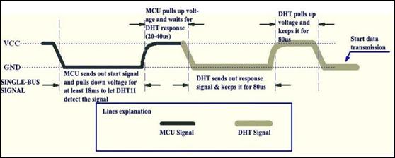
Once the DHT11 detects "Start Signal", it pulls the DATA pin down to "LOW" state and maintains the state for 80us to send the "Response Signal". The DHT11 then raises the DATA pin to "HIGH" state and maintains the state for 80us to notify that it is preparing to send data.
Data is transmitted on bit basis. All transmissions start with "LOW" voltage signal for 50us and end with "HIGH" voltage signal for a certain time. The holding time of "HIGH" voltage signal depends on whether the transmitted bit is "0" or "1". Bit "0" data lasts "HIGH" voltage for 26-28us, and bit "1" data lasts "HIGH" voltage for 70us. In the figure below, the left shows the signal of bit "0" and the right shows the signal of bit "1".
25.8.3.2 Writing Program with <WiringPi> Library
Here we will process the sensor's data with <WiringPi> Library. Wel use C language for development language.
Write the following program and save it in "sensor_temp_DHT11.c" file.
| /* Simple test program to test the wiringPi functions DHT11 test */ #include <wiringPi.h> #include <stdio.h> #include <stdlib.h> #include <stdint.h> #define MAXTIMINGS 85 #define DHTPIN 7 int dht11_dat[5] = { 0, 0, 0, 0, 0 };
void read_dht11_dat() { uint8_t laststate = HIGH; uint8_t counter = 0; uint8_t j = 0, i; float f; /* fahrenheit */
dht11_dat[0] = dht11_dat[1] = dht11_dat[2] = dht11_dat[3] = dht11_dat[4] = 0;
/* pull pin down for 18 milliseconds */ pinMode( DHTPIN, OUTPUT ); digitalWrite( DHTPIN, LOW ); delay( 18 );
/* then pull it up for 40 microseconds */ digitalWrite( DHTPIN, HIGH ); delayMicroseconds( 40 );
/* prepare to read the pin */ pinMode( DHTPIN, INPUT );
/* detect change and read data */ for ( i = 0; i < MAXTIMINGS; i++ ) { counter = 0; while ( digitalRead( DHTPIN ) == laststate ) { counter++; delayMicroseconds( 1 ); if ( counter == 255 ) { break; } } laststate = digitalRead( DHTPIN ); if ( counter == 255 ) break; /* ignore first 3 transitions */ if ( (i >= 4) && (i % 2 == 0) ) { /* shove each bit into the storage bytes */ dht11_dat[j / 8] <<= 1; if ( counter > 16 ) dht11_dat[j / 8] |= 1; j++; } }
/* check * we read 40 bits (8bit x 5 ) + verify checksum in the last byte * print it out if data is good */ if ( (j >= 40) && (dht11_dat[4] == ( (dht11_dat[0] + dht11_dat[1] + dht11_dat[2] + dht11_dat[3]) & 0xFF) ) ) { f = dht11_dat[2] * 9. / 5. + 32; printf( "Humidity = %d.%d %% Temperature = %d.%d *C (%.1f *F)\n", dht11_dat[0], dht11_dat[1], dht11_dat[2], dht11_dat[3], f ); }else { printf( "Data not good, skip\n" ); } }
int main( void ) { printf( "Raspberry Pi wiringPi DHT11 Temperature test program\n" ); if ( wiringPiSetup() == -1 ) exit( 1 ); while ( 1 ) { read_dht11_dat(); delay( 1000 ); /* wait 1 sec to refresh */ } return(0); } |
Here is a look at the contents of the above program.
■ When the program starts, this first initialize the GPIO with "wiringPiSetup( )" function.
■ This sets the DHTPIN pin on wiringPi basis to output with "pinMode( )" function.
■ With "digitalWrite( )" function, this sends "HIGH" signal first and wait 18ms, then output "LOW" signal and wait 40ms.
■ This sets the DHTPIN pin back to input with "pinMode( )" function.
■ This reads the pin value with "digitalRead( )" function to see if the state has changed, and if the state changes, this stores the value in "dht11_dat[ ]" variable.
■ This checks whether the data is correct, and if there is no problem, this outputd it to the screen.
Compile the written program to create a executable file. When compiling, specify <wiringPi> library as below so that compiler can refer to <WiringPi> library.
| gcc -Wall -o sensor_temp_DHT11 sensor_temp_DHT11.c -l wiringPi |
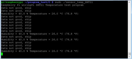
Execute the executable file created by compiling as below to check that it works properly. When everything is OK, the value of the sensor will be displayed on the screen.
| sudo ./sensor_temp_DHT11 |
25.8.3.3 Writing Program with <RPi.GPIO> Library
Here we will describe how to interface with a sensor using <RPi.GPIO> library.
We will use uses Python 3 for program development language. First, start Python 3 IDLE, write the following Python program, and store it in "sensor_temp_DHT11.py" file.
| import RPi.GPIO as GPIO import time
def bin2dec(string_num): return str(int(string_num, 2))
GPIO.setmode(GPIO.BCM)
while True : data = []
time.sleep(0.02) GPIO.setup(4,GPIO.OUT)
GPIO.output(4,GPIO.HIGH) time.sleep(0.025) GPIO.output(4,GPIO.LOW) time.sleep(0.02)
GPIO.setup(4, GPIO.IN, pull_up_down=GPIO.PUD_UP) # time.sleep(0.02)
for i in range(0,300): data.append(GPIO.input(4))
bit_count = 0 tmp = 0 count = 0 HumidityBit = "" TemperatureBit = "" crc = ""
try: # initial -- High # while data[count] == 1: # tmp = 1 # count = count + 1 # # response -- Low # while data[count] == 0: # tmp = 1 # count = count + 1 # # ready -- High while data[count] == 1: tmp = 1 count = count + 1
# fetch 32 bit data for i in range(0, 32): bit_count = 0
# bit start -- Low while data[count] == 0: tmp = 1 count = count + 1
# bit data -- High while data[count] == 1: bit_count = bit_count + 1 count = count + 1
# determin "0" or "1" by "High" count --count <= 2 – bit "0", count > 3 -- bit "1" if bit_count > 3: if i>=0 and i<8: # 0 ~ 7 bit HumidityBit = HumidityBit + "1" if i>=16 and i<24: # 16 ~ 23 bit TemperatureBit = TemperatureBit + "1" else: if i>=0 and i<8: # 0 ~ 7 bit HumidityBit = HumidityBit + "0" if i>=16 and i<24: # 16 ~ 23 bit TemperatureBit = TemperatureBit + "0"
except: # print ("ERR_Fetch Measurement") # exit(0) continue
# Fetch CRC try: for i in range(0, 8): bit_count = 0
# bit start -- Low while data[count] == 0: tmp = 1 count = count + 1
# bit data -- High while data[count] == 1: bit_count = bit_count + 1 count = count + 1
# determin "0" or "1" by "High" count --count <= 2 – bit "0", count > 3 -- bit "1" if bit_count > 3: # bit 1 crc = crc + "1" else: # bit 0 crc = crc + "0" except: # print ("ERR_Fetch CRC") # exit(0) continue
Humidity = bin2dec(HumidityBit) Temperature = bin2dec(TemperatureBit) Checkcrc = bin2dec(crc)
if int(Humidity) + int(Temperature) - int(Checkcrc) == 0: print ("Humidity:"+ Humidity +"%" + "\t Temperature:"+ Temperature +" C" + "\t CRC:"+ Checkcrc) else: print ("ERR_CRC Check")
continue
exit(0) |
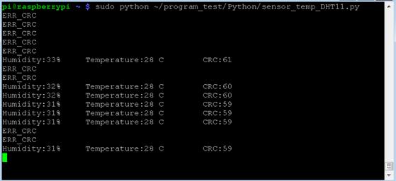
Execute the following program with "sudo" command on Terminal screen. The temperature value measured by the sensor will then be displayed continuously on the screen.
| sudo python sensor_temp_DHT11.py |
25.8.3.4 Raspberry Pi and Real Time Processing
The above two examples show that there are cases that data may be lost. This is because Raspberry Pi is not a system executed in real time. As the delay that occurs in the program is not accurate, transmission errors may occur sometimes in connection with external devices.
Since C is a lower level development language, we can control the GPIO pin more directly, so we can see that the error in the previous example of C language is relatively low.
One roundabout way to deal with this error is to modify the program and run the program several times to get the correct value
.