Published Book on Amazon
| All of IOT Starting with the Latest Raspberry Pi from Beginner to Advanced – Volume 1 | |
| All of IOT Starting with the Latest Raspberry Pi from Beginner to Advanced – Volume 2 |
출판된 한글판 도서
| 최신 라즈베리파이(Raspberry Pi)로 시작하는 사물인터넷(IOT)의 모든 것 – 초보에서 고급까지 (상) | |
| 최신 라즈베리파이(Raspberry Pi)로 시작하는 사물인터넷(IOT)의 모든 것 – 초보에서 고급까지 (하) |
Original Book Contents
25.7 Digital Input/Output
25.7.1 Digital Output – LED On/Off
Here we will try to implement an example of connecting a LED to Raspberry Pi and blinking the LED using a program.
25.7.1.1 Installing LED
When making the circuit, connect a LED, a resistor, and Raspberry Pi using a breadboard as shown below.
First, install a LED so that both legs are on separate rows on a breadboard. Then connect the LED to the GPIO connector of Raspberry Pi as shown below. Connect the LED long leg (+) to the physical number pin 11 (pin 0 on the wiringPi) and the LED short leg (-) to the physical number pin 6 (ground). We use the most common 5mm diameter LED for LED used in the circuit, and use 330Ω for the resistance.
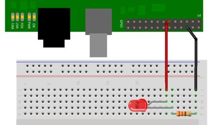
Figure 25‑18 Digital output – LED On/Off
25.7.1.2 Example of Using <WiringPi> Library
Here is a program using <WiringPi> library that shows a GPIO interface that blinks LED connected to Raspberry Pi. The program is written in C language here.
Write the following program and save it in "ledtest.c" file.
| #include <wiringPi.h> int main (void) { wiringPiSetup () ; pinMode (0, OUTPUT) ; for (;;) { digitalWrite (0, HIGH) ; delay (500) ; digitalWrite (0, LOW) ; delay (500) ; } return 0 ; } |
Here is a look at the contents of the above program.
■ This includes "wiringPi.h" header to use <WiringPi> library function in the program.
■ This initialize GPIO with "wiringPiSetup( )" function.
■ This sets pin 0 on wiringPi basis as output with "pinMode( )" function to.
■ This outputs HIGH and LOW signals at regular intervals with "digitalWrite( )" function. Here, the HIGH signal means a state in which a current flows, and the LOW signal means a state in which no current flows.
Compile the written program to create an executable file. When compiling, specify <wiringPi> library as below so that compiler can refer to <WiringPi> library.
| gcc -Wall -o ledtest ledtest.c -l wiringPi |
Execute the executable file created by compiling as below to check that it works properly. If everything goes well, the LED will blink once per second.
| ./ ledtest |
25.7.1.3 Example of <RPi.GPIO> Library
Here is a program using <RPi.GPIO> library that shows a GPIO interface that blinks LEDs connected to Raspberry Pi. The program is written in Python 3 language.
First, start Python 3 IDLE, write a simple Python program as follows, and save it in "ledtest.py".
| import RPi.GPIO as GPIO import time
GPIO.setmode( GPIO.BOARD) GPIO.setup(11, GPIO.OUT)
blink_count = int(raw_input("Enter LED Blink Count ->"))
for i in range(0, blink_count): GPIO.output(11, True) time.sleep(2) GPIO.output(11, False) time.sleep(2) print ("LED blink count ->%d" %(i+1) )
GPIO.cleanup() print ("LED blink Ended") |
Here is a look at the contents of the above program.
■ This imports "RPi.GPIO" to enable <RPi.GPIO> library function in the program.
■ This imports "time" to handle time related processing in the program.
■ This sets the pin numbering system to BOARD system with "setmode( )" function.
■ This sets pin 11 to output with "setup( )" function.
■ This receives the number of LED blinks with "raw_input( )" function.
■ This outputs "True" signals and "False" signals at regular intervals with "output( )" function. Here, the "True" signal means a state in which current flows, and the "False" signal means a state in which no current flows.
■ When all processing is complete, this resets the GPIO state to the initial state with "cleanup( )" function.
Execute the program as follows with "sudo" command on Terminal screen. You will then enter the number of times the LED blinks, and then the LED will blink at a periodic interval.
| sudo python ledtest.py |